Thursday 14 June 2018

Instrumentation P&ID symbols

Instrumentation P&ID symbols

What is P&ID?

Piping and instrumentation diagrams, or P&IDs, are used to create important documentation for process industry facilities. The shapes in this legend are representative of the functional relationship between piping, instrumentation, and system equipment units. We've broken them down into seven main groups: equipment, piping, vessels, heat exchangers, pumps, instruments, and valves.
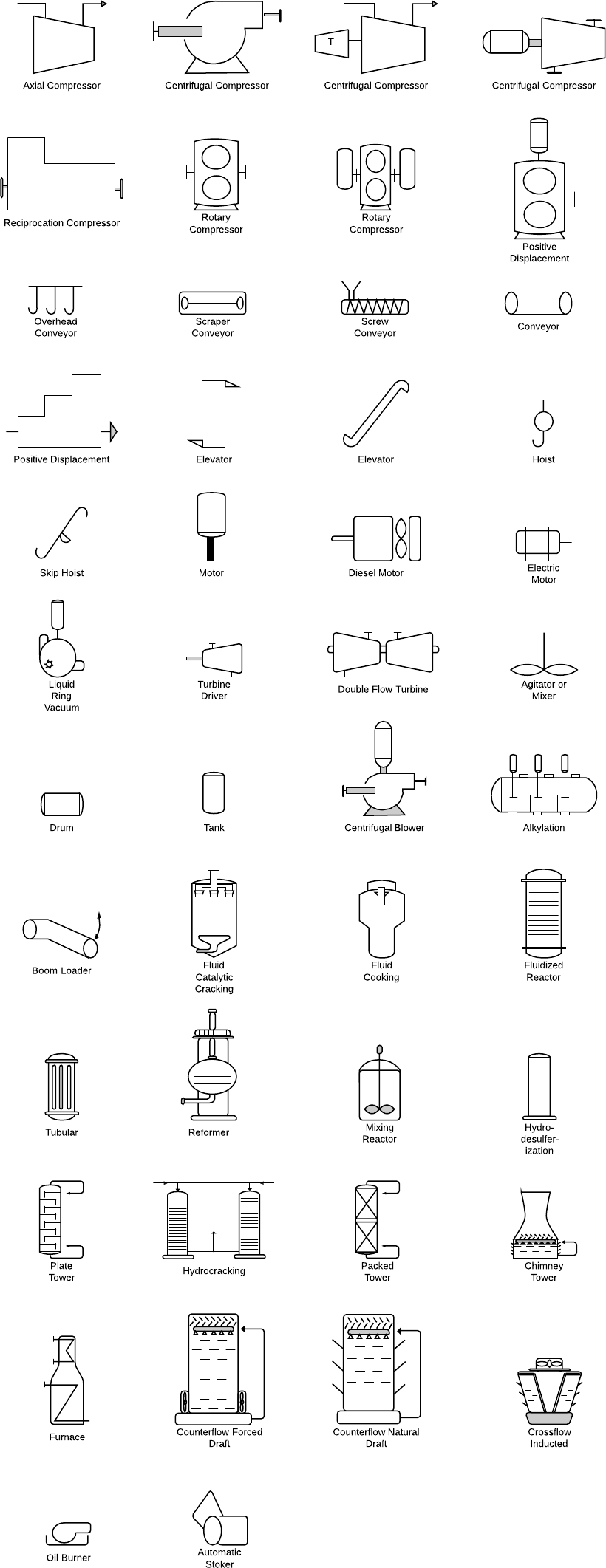
Equipment symbols

Equipment is comprised of miscellaneous P&ID units that don't fit into the other categories. This group includes hardware like compressors, conveyors, motors, turbines, vacuums, and other mechanical devices.
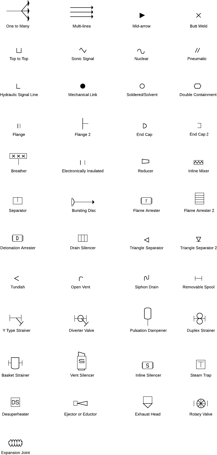
P&ID symbols

Piping symbols

A pipe is a tube that transports fluid substances. Piping can be made of various materials, including metal and plastic. The piping group is made up of one-to-many pipes, multi-line pipes, separators, and other types of piping devices.
piping P&ID symbol

Vessel symbols

A vessel is a container that is used to store fluid. It may also alter the characteristics of the fluid during storage. The vessels category includes tanks, cylinders, columns, bags, and other vessels.
vessel P&ID symbols

Heat exchanger symbols

A heat exchanger is a device that's designed to efficiently transfer heat from different areas or mediums. This category includes boilers, condensers, and other heat exchangers.
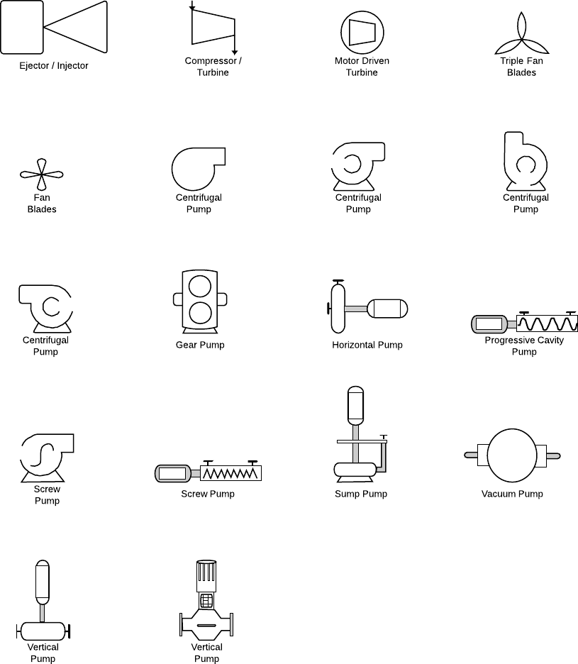
heat exchanger P&ID symbols

Pump symbols

A pump is a device that uses suction or pressure to raise, compress, or move fluids in and out of other objects. This section is comprised of both pumps and fans.
pump P&ID symbols

Instrument symbols

An instrument is a device that measures—and sometimes controls—quantities such as flow, temperature, angle, or pressure. The instruments group houses indicators, transmitters, recordings, controllers, and elements.
instrument P&ID symbols

Valve symbols

A valve regulates, directs, or controls the flow of a fluid by opening, closing, or partially obstructing passageways in a piping system.This category includes rotameters, orifices, and other types of valves.
valve P&ID symbol

Friday 11 May 2018

Control valves Interview questions and answers

  1. Control valves Interview questions and answers

    Question1. Why Do Different Control Valves Have Different Characteristics?

    Answer :
    • Some valves have an inherent characteristic that cannot be changed, such as full port ball valves and butterfly valves. For other valve types, such as globe, the characteristic can be changed to suit the application.
    • Ideally the inherent valve characteristic should be chosen to give an installed characteristic as close as possible to linear (see inherent vs installed characteristic). This enables the loop to remain tuned at all conditions with the same calibration settings.

  2. Question2. Definition Of Linear And Equal Percentage Characteristic?

    Answer :
    Linear – For equal stem movements the change of flow resulting from the movement is constant throughout the stroke.
    Equal Percentage – For equal stem movements the change of flow resulting from the movement is directly proportional to the flow rate immediately before the change took place.
    Besides the loop gain and installed characteristic considerations, equal percentage valve trim will generally give better rangeability and better control at low flow rates. Linear trim will give better control at flow rates over 50% of the valve capacity. 
  3. Question3. What Is The Trim In A Control Valve?

    Answer :
    The trim consists of the parts of the valve that affect the flow through the valve. In a standard globe valve the trim would just be the plug and seat. In a special valve the trim would consist of the plug, seat and retainer (or disk stack).
  4. Question4. Why Is Reduced Trim Required In Control Valves?

    Answer :
    • Control valves are sized according to the application requirements and must satisfy both Cv and velocity criteria.
    • Reduced trim is used where it is necessary for the valve to have a Cv capacity smaller than the maximum possible in that size of valve.
    • The most common reason for reduced trim is that the flow rate is low for the size of valve required – particularly where 25mm valves have been specified as the smallest size to be used. Some plants stipulate that no control valve should be less than two sizes smaller than the line size, other that the valve should not be less than half the line size.
    • The second reason is that on high pressure drop gas or vapour applications the valve invariably is sized on the outlet port velocity limits and the Cv required is much less than the full bore Cv.
  5. Question5. What Is Meant By Critical Pressure And Critical Temperature?

    Answer :
    Critical temperature is that above which a fluid cannot be liquefied by pressure alone. Critical pressure is the equilibrium or vapour pressure of a fluid at its critical temperature.
    1. Question6. Are Safety Valves, Regulators And Isolating Valves All Examples Of Control Valves?

      Answer :
      Normally the term control valve is used to describe a valve that controls flow with an externally adjustable variable restriction. Safety valves and isolating valves should not be referred to as control valves without a qualifier such as safety control valve or on/off control valve. Regulators should be referred to as self-regulating control valves to avoid confusion.
    2. Question7. Is Flow Through A Control Valve – Turbulent Or Laminar?

      Answer :
      • Flow through control valves is almost always turbulent.
      • Laminar flow takes place with liquids operating at low Reynolds numbers. This occurs with liquids that are viscous, working at low velocities. Laminar flow in gases and vapours very seldom will be experienced in process plants.
    3. Question8. What Is Cavitation?

      Answer :
      Cavitation is a condition that occurs in liquid flow where the internal pressure of the liquid, at some point falls below the vapour pressure and vapour bubbles form and at some other point downstream rises above the vapour pressure again. As this pressure recovers so the bubbles collapse, and Cavitation takes place
      It is possible to predict where cavitation will occur by looking at the pressure conditions and the valve recovery factor. However, it is important to recognise that the damage that occurs is dependent on the energy being dissipated and is thus flow dependent.Cavitation sounds like stones passing through the valve.
    4. Question9. What Effect Does The Positioner Cam Have On A Valve Characteristic?

      Answer :
      The feedback cam in the positioner controls the relationship between the control signal and valve position. With a linear cam at 50% signal the valve will be 50% open.
      It is possible to alter the apparent characteristic of a valve by changing the shape of the cam e.g. for a ball valve that has an inherent equal percent character it is possible to make it appear linear so that the flow rate through the valve at 50% signal is half of the maximum flow – the valve will however only be 25% open to achieve this result.
      From the control point of view there are advantages in doing this, but changing the valve characteristic and keeping the linear cam in the positioner is a better technical solution if it is possible.
    5. Question10. What Is Flashing?

      Answer :
      Flashing is a condition that occurs with liquid flow where the pressure falls below the vapour pressure and remains below it. There are then two phases flowing (i.e. liquid and vapour) downstream.
      Severe damage can occur inside a valve due to erosion caused by the impact of liquid droplets travelling at high speeds.
      1. Question11. What Is Choked Flow?

        Answer :
        • Choked flow (otherwise known as critical flow) takes place in a valve when an increase in pressure drop across the valve no longer has any effect on the flow rate through the valve. It occurs when the velocity of the gas or vapour reaches sonic (Mach 1) at the vena contracta.
        • Choked flow is not necessarily a problem in valves but does need to be taken into account in the Cv calculations. For liquids, choked flow indicates the onset of full cavitation, which usually requires special steps to be taken to reduce damage.
        • With clean gases there is no problem with choked flow. Use the choked pressure drop in any equation to calculate Cv or flow rates. High noise levels may be generated.
        • Solid particles in gas flow will cause erosion due to the high velocities involved. With liquids full cavitation will occur when the flow is choked.
        • High recovery valves, such as ball and butterfly, will become choked at lower pressure drops than low recovery valves such as globe which offer a more restricted flow path when fully open.
      2. Question12. How Can Cavitation Damage Be Contained?

        Answer :
        Three methods exist for treating cavitation in control valves – the first is to ensure that the plug and seat are made of a material that can resist the damage (e.g. stellite hard facing). The second is to control where the bubbles collapse and keep this away from vulnerable components (see Cav Control trim). The third is to control the pressure drop and velocities to ensure that the liquid pressure does not fall below the vapour pressure – thus eliminating cavitation altogether.
      3. Question13. How Can Flashing Damage Be Contained?

        Answer :
        Flashing cannot be eliminated in the valve – if the downstream pressure is less than the vapour pressure then flashing will occur.
        To minimise the damage:-
        • Hard face trim (using hard facing materials such as Stellite, or Tungsten Carbide)
        • Use more erosion resistant body material
        • Increase size of valve, thus reducing the velocity
        • Use angle valve – flow over plug
      4. Question14. Definition Of Linear And Equal Percent Characteristics?

        Answer :
        Equal Percent characteristics.
        The change of flow resulting from a fixed increment of valve travel is directly proportional to the flow immediately before the change took place.
        Linear characteristics.
        The change in flow resulting from a fixed increment of valve travel is constant throughout the whole stroke.
        General rules.
        • Use Equal Percent if in doubt.
        • Use Linear for level control.
        • Use Equal Percent for pressure control.
        • Use Linear when the pressure drop across the valve is a large proportion of the total pressure drop.
      5. Question15. How Is The Characteristic Determined In A Globe Valve?

        Answer :
        There are several ways of altering the characteristic in a globe valve depending on the particular design.
        • The most common is to use the profile on the front of the plug head. In this case the seat ring and retainer are not changed. If the plug is cage guided the characteristic of the valve is usually determined by the retainer or disk stack with the plug having a flat face. As the plug moves up, it uncovers more flow paths.
        • A series of small holes at the bottom of the retainer with larger holes at the top will give a bi-linear characteristic, which can be designed to give results similar to equal percent.
      6. Question16. Is The Velocity Of A Fluid In A Control Valve Critical?

        Answer :
        The velocity is one of the more important considerations in sizing a control valve. For long life on liquid applications the velocity at the exit of the valve body should be less than 10 m/s. This compares with generally accepted line velocities of about 3 m/s, which explains why control valves often are smaller than the line size.
        On gases and vapours the velocity at the exit of the valve body should be less than 0.33 Mach (1/3rd of sonic) for noise control valves and less than 0,5 Mach where noise is not a consideration.
      7. Question17. What Is The Difference Between A Liquid, A Vapour And A Gas?

        Answer :
        These are all different states or phases in which a fluid can exist. H20 exists as a solid (ice), liquid (water), vapour (saturated steam), and a gas (superheated steam) – it depends on the temperature and pressure which phase is current. Practically the most significant difference between liquids and vapours/gases is the compressibility. Liquids are for most practical purposes incompressible where as the density of gas and vapours varies with pressure.
      8. Question18. What Is A Desuperheater And How Does It Differ From An Attemporator?

        Answer :
        • A desuperheater is a device that is used to control the addition of water to superheated steam to reduce the temperature to within 10°C of saturation.
        • An attemporator also adds water to steam to control its temperature but the set point temperature is higher and the downstream steam is still superheated.
        • Generally desuperheaters are used in process plants where the steam is used for heating. Attemporators are used more in power stations for interstage temperature control.
      9. Question19. What Is The Difference Between Installed And Inherent Characteristics?

        Answer :
        The inherent characteristic is a plot of the flow rate through a valve (or Cv) against percentage opening with a constant pressure drop across the valve.
        This is the result of a workshop test where the upstream and downstream pressure are held constant and the only variables are the flow rate and opening of the valve.
        The installed characteristic is the plot of flow against opening using actual pressure drops experienced in practice. Due to the fact that in most applications the pressure drop increases as the flow rate drops, the installed characteristic will normally change from =% towards linear, and from linear towards quick opening.
      10. Question20. Why Are Control Valves Sometimes Very Noisy?

        Answer :
        Noise is created by an object vibrating. Valve components will tend to vibrate whenever they are subjected to high velocity turbulent flow. Standard control valves will therefore tend to be noisy on high pressure drop applications particularly where flow rates are high, since the low pressure experienced downstream of the seat ring (at the vena contracta) is accompanied by very high velocities reaching as high as the speed of sound. Special low noise valves are designed to drop pressure gradually so that velocities are controlled at low levels.
      11. Question21. Can Two Control Valves Be Used In Series In High Pressure Drop Applications?

        Answer :
        Dropping the pressure across two valves rather than one is theoretically better. However, in practice, the two valves will not usually control well together unless the process can operate with a very low proportional band with slow response times.
        A better, and usually less expensive approach is to use a valve that is designed with multiple pressure drop restrictions inside the trim.
      12. Question22. Can Two Control Valves Be Used In Parallel To Handle High Turndown Applications?

        Answer :
        Two valves in parallel working on split range signals can give very high turndown capability. The situation that should be avoided if possible is that the larger valve operates in the “cracked open” position – one way to avoid this is to program the PLC or DCS to shut the small valve and use only the larger unit once the capacity of the small valve is exceeded.
        An alternative to two valves in parallel is to select a valve with a high rangeability such as a vee-ported ball valve.
      13. Question23. What Is The Difference Between Rangeability And Turndown?

        Answer :
        Generally the term rangeability is used to describe the capability of a control valve (i.e. the ratio of the maximum Cv of the valve to the minimum Cv at which it can control) whereas the term turndown is generally used to describe the requirement of an application (i.e. ratio of Cv at maximum conditions to Cv at minimum condition).
        Note that the rangeability of a valve must be greater than the ratio of the Cv of the valve when fully open to the calculated Cv for the minimum conditions of the application.
        • Turndown applies to the application and is the ratio of the calculated Cv at maximum conditions to the calculated Cv at minimum
        • Rangeability applies to the valve and is the ratio of the Cv of the valve fully open to the minimum Cv at which it can control
        • The rangeability of the selected valve must exceed the turndown requirements of the application.
      14. Question24. What Process Date Is Required To Size A Control Valve?

        Answer :
        • Medium – What is passing through the valve? – if it is a special liquid give specific gravity (at flowing temperate), critical pressure, vapour pressure and viscosity.
        • Pressures – What is the maximum pressure that the valve needs to be rated for? What are the upstream and downstream pressures for each of the maximum, normal and minimum flow rates.
        • Flow rates – Maximum, normal and minimum. The maximum is used to select the valve size, the minimum to check the turndown requirement and the normal to see where the valve will control.
        • Temperature – Maximum temperature for design plus temperatures at maximum, normal and minimum flow conditions.
        • Please see the relevant enquiry sheets for additional information that may assist in the sizing and selection of the control valve required.
      15. Question25. What Is Incipient Cavitation?

        Answer :
        Incipient means “starting” – “incipient cavitation” begins when the pressure first dips below the vapour pressure and continues until the flow becomes choked at which point “full cavitation” is said to take place.
      16. Question26. What Is The Difference Between A Diffuser Plate And A Choke?

        Answer :
        A diffuser is a plate with a large number of small holes in it that is installed in the downstream pipework. On gas and vapour applications it creates a back pressure between the valve and plate, and this enables a smaller value to be selected than would otherwise be possible, due to the lower velocity at maximum flow. The overall noise level produced will be lower as the overall number of pressure drop stages are increased.
        A choke is a restriction orifice and is a plate with one central hole. It is used with liquid flows and is also installed in the downstream pipe work to create backpressure. The purpose is to reduce the pressure drop across the valve at the maximum flow rate either to eliminate cavitation or to reduce the intensity of the damage to the valve.
      17. Question27. What Is A Field Reversible Actuator?

        Answer :
        The actuators for many control valves are either spring-to-open or spring-to-close. The Mitech control valve actuator has all the parts necessary to reverse the action – this will normally take place in a workshop on site.
      18. Question28. Will Separable Flanged Valves Seal In A Pipeline?

        Answer :
        The sealing face is part of the valve body and so the separable flanges are only there to hold the body in the line – they are not required to seal.
      19. Question29. What Is Vapour Pressure?

        Answer :
        • The terms vapour pressure applies to a liquid, and is the natural equilibrium pressure that exists inside a closed vessel containing the liquid.
        • Vapour pressure varies with temperature.
        • The vapour pressure of water at ambient temperature of about 25°C is in the order of 4 kPa(a). This means that water will boil at 25°C if the external pressure is reduced to an absolute pressure of 4 kPa. At 100°C the vapour pressure of water is 101 kPa(a), which means that water will boil at 100° C at sea level where the atmospheric pressure is about 101 kPa(a).
      20. Question30. Specific Gravity Is The Ratio Of The Density Of A Liquid To The Density Of Water – What Is The Specific Gravity Of Gas?

        Answer :
        The specific gravity of gas is the ratio of the density of the gas to the density of air both measured at standard conditions of 101,3kPa and 15°C .
      21. Question31. What Is Meant By Cryogenic?

        Answer :
        Cryogenic valves operate at temperatures below minus 100°C.
        These valves have extended bonnets to remove the stuffing box and actuator away from the source of cold and are made of materials such as stainless steel Monel or bronze that do not become too brittle at these temperatures.
      22. Question32. What Materials Can Be Used For Oxygen Service?

        Answer :
        • Monel, bronze and austenitic stainless steel (e.g. 316) are the best materials for oxygen service in order of preference. The higher the velocity the better the material to be used.
        • Velocities should not exceed 40 m/s in the valve body with Monel and bronze and should be less than 20 m/s with stainless steel.
      23. Question33. Why Do Oxygen Valves Require De-greasing?

        Answer :
        In the presence of most oils and greases oxygen will burn or explode. Even the oil deposited on a component by an uncovered hand is sufficient to cause a problem, which is why plastic gloves should be used when building degreased valves.
      24. Question34. Why Do Some Control Valve Actuators Have A Small Internal Fail Action Spring And Some Are External And Much Larger?

        Answer :
        A piston actuator piped up double acting and operating with full supply pressure of about 500 kPa is very stiff and can normally operate satisfactorily with the flow direction either under the plug or over. This enables the flow direction to be chosen to assist with the fail action, which means that only a small bias spring is necessary inside the actuator to start initial movement in the right direction in the event of air failure. In the case of diaphragm actuated valves, the stiffness is much lower and so the flow direction must always be under the plug, resulting in the need of a heavy spring to give fail closed action. This cannot be fitted inside the actuator.
      25. Question35. Why Is Live Loading Sometimes Offered On Valves?

        Answer :
        Live loading reduces the need for routine maintenance in the plant.
        Live loading is recommended on applications where a leak along the valve shaft would be likely to cause damage to the shaft and packing. High-pressure water and steam applications are examples of where live loading is advantageous.
      26. Question36. Why Is Energy Dissipation An Important Factor In Control Valve Selection?

        Answer :
        All Control valves cause pressure drop in the fluid as it passes through the valve. Since pressure is a form of Potential Energy, this means that a certain amount of energy is converted from potential energy into some other form. The higher the Pressure Drop and the greater the flow rate then more energy will be dissipated. Depending on the type of valve and the trim design this energy can cause significant damage to valve components due to cavitations and high velocities, or can be environmentally unfriendly because of high noise levels produced. Through the careful choice of valve type and correct trim design it is possible to minimize the adverse effects of high levels of energy dissipation.

Thursday 3 May 2018

Instrumentation interview questions and answers

1.What is an Indicator?

An indicator is a human readable device that displays information about the process.

What is a Transducer?

A transducer is device that translates a mechanical signal into an electrical signal.
What is a Transmitter?
A transmitter is a device that converts a reading from a sensor or transducer into a standard signal and transmit that signal to a monitor or controller.

What Are The Primary Elements Usedfor Flow Measurement?

Answer :
The primary elements used for flow measurement are:
  1. Orifice Plate.
  2. Venturi tube.
  3. Pitot tube.
  4. Annubars.
  5. Flow Nozzle.
  6. Weir & Flumes.
  7. What Are The Different Types Of Orifice Plates And State Their Uses?
  8. Answer :
    The different types of orifice plates are:
    1. Concentric.
    2. Segmental.
    3. Eccentric.
    CONCENTRIC: The concentric orifice plate is used for ideal liquid as well as gases and steam service. This orifice as a hole in concentric and hence known as concentric orifice.
    Eccentric & Segmental: The eccentric orifice plate has a hole eccentric. The use this is made in viscous and sherry flow measurement.
    The segmental orifice place has the hole in the form segment of a circle. This is used for colloidal and sherry flow measurement.
  9. What Is The Seal Liquid Used For Filling Impulse Lines On Crude And Viscous Liquid?

    Answer :
    Glycol.
  10. How Do You Carry Out Piping For A Different Pressure Flow Transmitter On Liquids, Gas And Steam Services? Why?

    Answer :
    Liquid lines: On liquid lines the transmitter is mounted below the orifice plate. Since liquids have a property of self draining.
    Gas Service: On gas service the transmitter is mounted above the orifice plate because Gases have a property of self venting and secondly condenlate formation.
    Steam Service: On steam service the transmitter is mounted below the orifice plate with condenlate pots. The pots should be at the same level.
  11.  An Operator Tells You That Flow Indication Is More? How Would You Start Checking?

    Answer :
    1. First flushing the transmitter. Flush both the impulse lines. Adjust the zero by equalizing if necessary. If still the indication is more then.
    2. Check L.P. side for choke. If that is clean then.
    3. Check the leaks on L.P. side. If not.
    4. Calibrate the transmitter.
    5. How Do You Do A Zero Check On A D.p. Transmitter?

      Answer :
      Close one of the valve either H.P. or L.P. open the equalizing valve. The O/P should read zero.
    6. A solenoid is electrically operated valve. It consists of solenoid coil in which magnetic plunger moves. This plunger is connected to the plug and tends to open or close the valve. There are two types of solenoid valves:

      1. Normally Open
      2. Normally closed

      Use: It is used for safety purpose in different electric work
    7. Types of bourdon tubes:
      1. C type
      2. Spiral
      3. Helix
    8. Primary elements of measuring pressure are:
      a. Bourdon Tube
      b. Diaphragm
      c. Capsule
      d. Bellows
      e. Pressure springs
      These elements are known as elastic deformation pressure elements.
    9. Valve positioner can be used for following reasons:
      a. Quick action
      b. Valve hysterisis
      c. Viscous liquids
      d. Split range.
      e. Line pressure changes on valve
      f. Bench set not standard
      g. Reverse valve operations
    10. Pressure gauge includes following components:
      a. ‘C' type bourdon tube.
      b. Connecting link
      c. Sector gear
      d. Pinion Gear
      e. Hair spring
      f. Pointer
      g. Dial

      Use of hair spring: Hair spring is responsible for controlling torque. It is also used to eliminate any play into linkages.
    11. excessive pressure to your differential pressure transmitter, you could damage your instrument. This is known as over-ranging the transmitter. 

      A three-way manifold valve is a device that prevents the instrument from being over-ranged. It also allows the isolation of the transmitter from the process loop (an option which could be used generaly for maintenance or re-calibration or fitting new equipment).